As an electronics maker, you’re probably comfortable with circuits, code, and microcontrollers. But when your project needs to move something in the real world, you enter the realm of mechanical engineering. Understanding mechanical linkages can transform a good project into a great one.
This guide covers the most useful linkage types for maker projects, when to use each one, and practical design tips that will save you hours of trial and error.
What is a mechanical linkage?
A mechanical linkage is a system of rigid bodies (links) connected by joints that converts one type of motion into another. Think of it as “motion transformation” — you can change:
- Rotary to linear: a spinning motor shaft into back-and-forth motion.
- Linear to rotary: a pushing piston into wheel rotation.
- Direction: change the angle or axis of motion.
- Force/speed: trade speed for force (mechanical advantage).
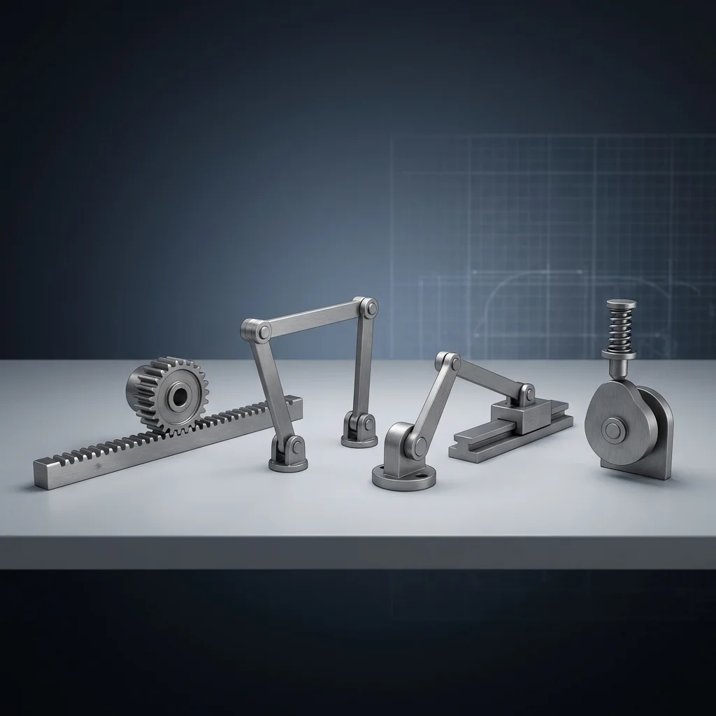
The six essential linkages for makers
Master these six and you’ll be able to solve 90% of mechanical motion problems in maker projects:
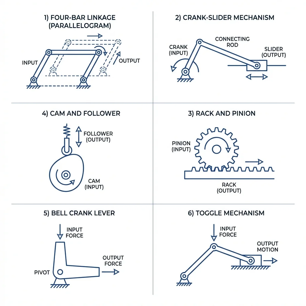
1. Rack and pinion
2. Crank-slider mechanism
3. Four-bar linkage (parallelogram)
4. Cam and follower
5. Bell crank (L-shaped lever)
6. Toggle mechanism
Quick reference: which linkage to choose?
Use this comparison to quickly identify the right linkage for your project:
| I need to… | Use this linkage |
|---|---|
| Convert motor rotation to linear sliding | Rack and pinion or crank-slider |
| Move something in a complex curved path | Four-bar linkage |
| Change direction of motion by 90° | Bell crank |
| Get precise, timed motion from rotation | Cam and follower |
| Clamp or press with huge force | Toggle mechanism |
| Keep parallel orientation during motion | Parallelogram linkage (four-bar) |
Design considerations
Material selection
Wood / MDF
Great for prototyping. Cheap, easy to cut, but not durable for long-term use.
3D-printed (PLA/PETG)
Perfect for custom shapes. Use PETG for better strength. Add metal pins for pivot joints.
Aluminium
Lightweight, strong, easy to machine. Ideal for final production parts.
Steel
Maximum strength and durability. Use for high-load or high-wear applications.
Joint types
- Pin joints (revolute): allow rotation only. Use bolts with nylon washers or bronze bushings for smooth operation.
- Sliding joints (prismatic): allow linear sliding. Use linear bearings or PTFE surfaces.
- Ball joints: allow rotation in all directions. Great for 3D linkages.
Common mistakes to avoid
- Overconstraining: adding too many links that fight each other. A mechanism should have exactly one degree of freedom (usually).
- Dead points: positions where the linkage locks up or has infinite force requirements. Test the full range of motion.
- Ignoring friction: more joints = more friction. Use bearings or lubricants for smooth operation.
- Poor tolerances: loose fits create backlash. Tight fits bind and wear quickly. Aim for 0.1–0.2 mm clearance.
Practical project examples
| Project | Linkage | Why it works |
|---|---|---|
| 3D printer axis | Rack & pinion | Precise linear motion from stepper motor |
| Walking robot leg | Four-bar | Creates natural walking path from rotation |
| Desk lamp arm | Parallelogram | Keeps lamp head level while moving |
| Air compressor | Crank-slider | Converts motor spin to piston pumping |
| Gripper claw | Toggle | Strong grip force at closed position |
Summary
Mechanical linkages are the bridge between your electronics and the physical world. Understanding these six fundamental mechanisms will dramatically expand what you can build:
- Rack & pinion — precise rotary-to-linear conversion.
- Crank-slider — continuous reciprocating motion.
- Four-bar — complex motion paths from simple rotation.
- Cam & follower — programmable motion timing.
- Bell crank — 90° direction change.
- Toggle — massive mechanical advantage.