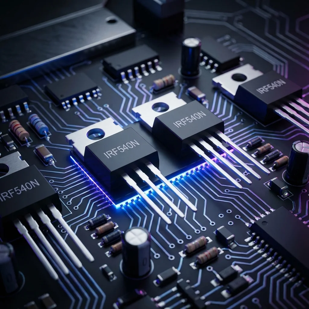
If there’s one component that has revolutionized modern electronics, it’s the MOSFET (Metal-Oxide-Semiconductor Field-Effect Transistor). From the power management in your smartphone to the motor controllers in electric vehicles, MOSFETs are everywhere. In this guide we’ll focus on the N-channel MOSFET — the most popular type — and explore why it’s the go-to choice for makers and engineers alike.
1. What is an N-channel MOSFET?
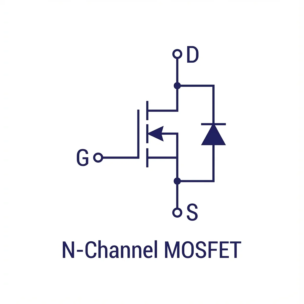
An N-channel MOSFET is a three-terminal semiconductor device used primarily as an electronic switch or amplifier. The three terminals are:
- Gate (G): The control terminal. Applying voltage here controls current flow.
- Drain (D): Where current flows INTO the device (in switching applications).
- Source (S): Where current flows OUT of the device (connected to ground in low-side switching).
2. How does an N-channel MOSFET work?
The operation of an N-channel MOSFET is elegantly simple and revolves around voltage control:
The “OFF” state
When no voltage (or voltage below the threshold) is applied to the Gate relative to the Source, the MOSFET acts like an open switch. No current flows between Drain and Source, regardless of the voltage applied across them.
The “ON” state
When a voltage greater than the threshold voltage (VGS(th)) is applied between Gate and Source, a conductive channel forms between Drain and Source. Current can now flow freely — the MOSFET acts like a closed switch.
The physics behind it
When positive voltage is applied to the Gate, it creates an electric field that attracts electrons to the region beneath the Gate oxide. This forms an N-type channel (hence “N-channel”) between the Drain and Source, allowing electrons to flow. The higher the Gate voltage (above threshold), the wider and more conductive this channel becomes.
3. Why N-channel over P-channel?
While both N-channel and P-channel MOSFETs exist, N-channel is overwhelmingly preferred in most applications. Here’s why:
| Characteristic | N-channel MOSFET | P-channel MOSFET |
|---|---|---|
| Charge carrier | Electrons (faster) | Holes (slower) |
| On-resistance (RDS(on)) | Lower (better efficiency) | 2–3× higher for same die size |
| Switching speed | Faster | Slower |
| Cost | Generally cheaper | More expensive |
| Availability | Wide selection | Limited options |
| Gate drive | Positive voltage (easy with MCUs) | Negative relative to source (complex) |
| Typical use | Low-side switching (load to V+) | High-side switching (load to GND) |
When to use P-channel MOSFETs
Despite these advantages, P-channel MOSFETs are still useful for:
- High-side switching where you need to control the positive supply line
- Reverse-polarity protection circuits
- Push-pull output stages (paired with N-channel)
- Battery disconnect circuits
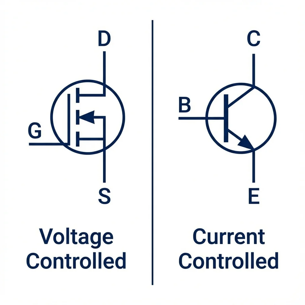
4. MOSFET vs BJT: the showdown
Before MOSFETs became dominant, BJTs (bipolar junction transistors) were the standard switching device. Understanding the differences helps you choose the right component for your project.
| Characteristic | MOSFET | BJT |
|---|---|---|
| Control method | Voltage-controlled (gate voltage) | Current-controlled (base current) |
| Input impedance | Extremely high (>10 MΩ) | Low (~1 kΩ) |
| Drive current required | Virtually zero (capacitive) | Continuous base current needed |
| Switching speed | Very fast (nanoseconds) | Moderate (storage time delay) |
| Saturation voltage | RDS(on) × ID (can be very low) | VCE(sat) typically 0.2–0.7 V |
| Thermal stability | Negative temp coefficient (self-limiting) | Positive temp coefficient (thermal-runaway risk) |
| Parallel operation | Easy (current sharing) | Difficult (requires balancing) |
| Best for | Power switching, PWM, motor control | Linear amplification, low-power switching |
5. Practical circuit: MOSFET motor control
Let’s look at a real-world application — controlling a DC motor with an N-channel MOSFET from an Arduino:
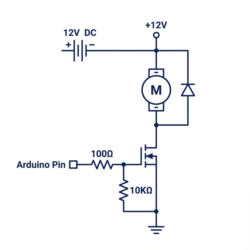
Circuit components
- MOSFET: IRF540N, IRLZ44N, or similar logic-level N-channel
- Gate resistor (100 Ω): limits inrush current to gate capacitance
- Pull-down resistor (10 kΩ): ensures the MOSFET stays OFF when the GPIO is floating
- Flyback diode (1N4007): protects against back-EMF from the motor
// Arduino MOSFET motor control with PWM
const int motorPin = 9;  // PWM-capable pin

void setup() {
    pinMode(motorPin, OUTPUT);
}

void loop() {
    // Ramp up motor speed
    for (int speed = 0; speed <= 255; speed += 5) {
        analogWrite(motorPin, speed);
        delay(50);
    }

    delay(1000);

    // Ramp down motor speed
    for (int speed = 255; speed >= 0; speed -= 5) {
        analogWrite(motorPin, speed);
        delay(50);
    }

    delay(1000);
}6. Common N-channel MOSFETs for makers
| Part number | VDS | ID | RDS(on) | VGS(th) | Logic level? |
|---|---|---|---|---|---|
| IRLZ44N | 55 V | 47 A | 22 mΩ | 1–2 V | Yes |
| IRL540N | 100 V | 36 A | 44 mΩ | 1–2 V | Yes |
| 2N7000 | 60 V | 200 mA | 1.2 Ω | 1–2.5 V | Yes |
| IRF540N | 100 V | 33 A | 44 mΩ | 2–4 V | No (needs 10 V gate) |
| IRF3205 | 55 V | 110 A | 8 mΩ | 2–4 V | No (needs 10 V gate) |
7. Key takeaways
- N-channel MOSFETs are voltage-controlled switches — apply voltage to the gate to turn ON.
- N-channel is preferred over P-channel due to lower RDS(on), faster switching, and easier driving.
- MOSFETs beat BJTs for power switching because they require no continuous drive current and have higher efficiency.
- Use logic-level MOSFETs (IRLZ44N, 2N7000) for direct microcontroller interfacing.
- Always use flyback diodes when switching inductive loads.
- Include a gate pull-down resistor (10 kΩ) to prevent floating-gate issues.
With this knowledge, you’re ready to harness the power of N-channel MOSFETs in your projects. Whether you’re building a motor controller, LED dimmer, or high-power switching circuit, the humble MOSFET will be your most versatile ally.