4-DOF Robotic Arm Controller
Build a fully functional 4-degree-of-freedom robotic arm controlled by Arduino! This advanced project uses servo motors for precise movement, potentiometers for manual control, and can be programmed to record and playback sequences. Great for learning robotics fundamentals and servo control.
Project Overview
This robotic arm project teaches fundamental concepts of robotics including servo control, coordinate systems, and motion programming. The arm has 4 degrees of freedom: base rotation, shoulder, elbow, and gripper - allowing it to pick up and place small objects.
You'll control the arm using four potentiometers that map your hand movements to servo positions. The code also includes a record/playback feature - record a sequence of movements and play them back automatically for repetitive tasks.
💡 What You'll Learn
- Controlling multiple servo motors simultaneously
- Reading analog inputs and mapping to servo angles
- Understanding degrees of freedom in robotics
- Implementing motion recording and playback
- Managing power requirements for multiple servos
- Smooth motion interpolation techniques
Components Required
Circuit Diagram
For a practical 4-DOF robotic arm, using a PCA9685 16-channel PWM driver is essential. It allows you to control multiple servos using only two I2C pins while providing a dedicated high-current power terminal for the motors, preventing the Arduino from overheating.
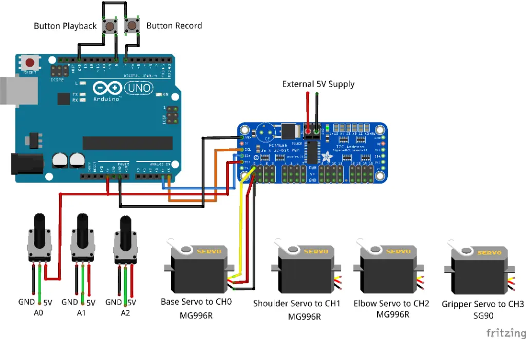
Fig 1: Practical Wiring Architecture using PCA9685 and External Power
🔍 Connection Master Table
| Component | Arduino Pin | PCA9685 Pin | Notes |
|---|---|---|---|
| PCA9685 Logic | 5V / GND | VCC / GND | Logic Power |
| I2C Bus | A4 / A5 | SDA / SCL | Serial Comm |
| Servo Power | N/A | V+ / GND Terminal | 5V 4A External |
| Base Servo | N/A | Channel 0 | MG996R (L/R) |
| Shoulder Servo | N/A | Channel 1 | MG996R (U/D) |
| Elbow Servo | N/A | Channel 2 | MG996R (Reach) |
| Gripper Servo | N/A | Channel 3 | SG90 (Grab) |
| Potentiometers | A0 - A3 | Center Wiper | Manual Control |
| Rec/Play Buttons | D7 & D8 | Pin 1 | Tactile Input |
👨🏫 Wiring Logic
Connect the SDA and SCL pins of the PCA9685 to the Arduino's A4 and A5 respectively. Each servo connects to the 3-pin headers on the breakout board (PWM Channel 0-3). Ensure the external 5V power is connected to the blue terminal block on the PCA9685.
Understanding 4-DOF
DOF stands for "Degrees of Freedom" - each independent axis of movement:
🦾 The Four Joints
Base (J1): Rotates the entire arm left/right (0-180°)
Shoulder (J2): Lifts the arm up/down from the base (0-180°)
Elbow (J3): Bends the forearm up/down (0-180°)
Gripper (J4): Opens and closes to grab objects (0-90°)
⚠️ Power Warning
Never power multiple servos from Arduino's 5V pin - it cannot supply enough current! Use an external 5V 4A power supply. Connect all grounds together (Arduino GND + Power Supply GND).
Step-by-Step Instructions
Assemble the Mechanical Arm
Follow your arm kit instructions to assemble the mechanical structure. Mount the high-torque MG996R servos at the base, shoulder, and elbow. Use the SG90 for the lighter gripper mechanism.
Set Up Power Distribution
Connect your 5V power supply to a breadboard power rail. Connect all servo power wires (red) to this rail. Connect all servo grounds (brown/black) to another rail, and tie this to Arduino GND.
Wire the Servo Signal Lines
Connect servo signal wires (orange/yellow) to Arduino digital pins: Base to D3, Shoulder to D5, Elbow to D6, Gripper to D9. These are PWM-capable pins.
Connect the Potentiometers
Wire four potentiometers: left pin to GND, right pin to 5V, middle (wiper) to analog pins A0-A3. Each pot controls one joint of the arm.
Add Control Buttons
Connect two push buttons: RECORD button to D7, PLAY button to D8. Use internal pull-up resistors (INPUT_PULLUP) to simplify wiring.
Upload and Calibrate
Upload the code, then test each joint individually. Adjust the servo angle limits in code to prevent mechanical binding or collisions.
Arduino Code
// 4-DOF Robotic Arm Controller with PCA9685
// MakersDeck Arduino Project

#include <Wire.h>
#include <Adafruit_PWMServoDriver.h>

// Create the PWM driver object
Adafruit_PWMServoDriver pwm = Adafruit_PWMServoDriver();

// PCA9685 Channel definitions
#define BASE_CH 0
#define SHOULDER_CH 1
#define ELBOW_CH 2
#define GRIPPER_CH 3

// Servo Pulse definitions (typical for MG996R/SG90)
#define SERVOMIN  150 // Minimum pulse length count
#define SERVOMAX  600 // Maximum pulse length count
#define SERVO_FREQ 50 // Analog servos run at ~50 Hz

// Potentiometer Pin definitions
#define POT_BASE A0
#define POT_SHOULDER A1
#define POT_ELBOW A2
#define POT_GRIPPER A3

#define BTN_RECORD 7
#define BTN_PLAY 8

// Recording storage
#define MAX_STEPS 100
int recording[MAX_STEPS][4];
int stepCount = 0;

void setup() {
    Serial.begin(9600);

    pwm.begin();
    pwm.setOscillatorFrequency(27000000);
    pwm.setPWMFreq(SERVO_FREQ);

    pinMode(BTN_RECORD, INPUT_PULLUP);
    pinMode(BTN_PLAY, INPUT_PULLUP);

    // Center all servos
    setServoAngle(BASE_CH, 90);
    setServoAngle(SHOULDER_CH, 90);
    setServoAngle(ELBOW_CH, 90);
    setServoAngle(GRIPPER_CH, 90);

    Serial.println("Robotic Arm Ready (PCA9685)!");
}

void loop() {
    // Read potentiometers
    int baseAngle = map(analogRead(POT_BASE), 0, 1023, 0, 180);
    int shoulderAngle = map(analogRead(POT_SHOULDER), 0, 1023, 0, 180);
    int elbowAngle = map(analogRead(POT_ELBOW), 0, 1023, 0, 180);
    int gripperAngle = map(analogRead(POT_GRIPPER), 0, 1023, 0, 90);

    // Move servos via PCA9685
    setServoAngle(BASE_CH, baseAngle);
    setServoAngle(SHOULDER_CH, shoulderAngle);
    setServoAngle(ELBOW_CH, elbowAngle);
    setServoAngle(GRIPPER_CH, gripperAngle);

    // Check record button
    if (digitalRead(BTN_RECORD) == LOW) {
        if (stepCount < MAX_STEPS) {
            recording[stepCount][0] = baseAngle;
            recording[stepCount][1] = shoulderAngle;
            recording[stepCount][2] = elbowAngle;
            recording[stepCount][3] = gripperAngle;
            stepCount++;
            Serial.print("Recorded step: ");
            Serial.println(stepCount);
        }
        delay(200);
    }

    // Check play button
    if (digitalRead(BTN_PLAY) == LOW && stepCount > 0) {
        Serial.println("Playing sequence...");
        playSequence();
    }
    delay(20);
}

void setServoAngle(uint8_t n, double angle) {
    double pulselen = map(angle, 0, 180, SERVOMIN, SERVOMAX);
    pwm.setPWM(n, 0, pulselen);
}

void playSequence() {
    for (int i = 0; i < stepCount; i++) {
        setServoAngle(BASE_CH, recording[i][0]);
        setServoAngle(SHOULDER_CH, recording[i][1]);
        setServoAngle(ELBOW_CH, recording[i][2]);
        setServoAngle(GRIPPER_CH, recording[i][3]);
        delay(100);
    }
    Serial.println("Sequence complete!");
}
Upgrade Ideas
🔧 Take It Further
- Add smooth motion with servo easing libraries
- Implement inverse kinematics for X/Y/Z control
- Use PCA9685 for more precise servo control
- Add Bluetooth control via smartphone app
- Store recordings in EEPROM for persistence
- Add joystick control as an alternative input