Distance measurement is one of the most fundamental capabilities in robotics, automation, and IoT projects. From simple obstacle detection to precision manufacturing, choosing the right distance sensor can make or break your project. This comprehensive guide covers all major types of distance sensors, their working principles, and when to use each one.
1. Ultrasonic distance sensors
Ultrasonic sensors are the workhorses of hobbyist distance measurement. They use sound waves (typically 40 kHz) to measure distance by calculating the time it takes for an echo to return.
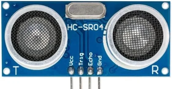
HC-SR04
The most popular ultrasonic sensor for Arduino and ESP32 projects. Affordable and reliable for basic robotics.
Range: 2–400 cm · accuracy ±3 mm · 5 V logic.
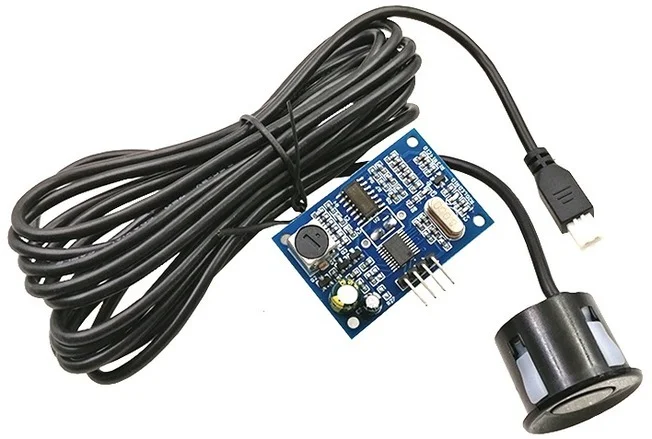
JSN-SR04T (waterproof)
Weatherproof variant with a separated probe, ideal for outdoor applications and liquid-level measurement.
Range: 25–450 cm · IP67 rated · 2.5 m cable.
How ultrasonic sensors work
The sensor emits a burst of ultrasonic pulses and listens for the echo. The time between transmission and reception is measured, and distance is calculated using:
Distance = (Time × Speed of Sound) / 2

// Speed of sound ≈ 343 m/s at 20°C
// Division by 2 because sound travels TO the object and BACK
HC-SR04 Arduino code:
const int trigPin = 9;
const int echoPin = 10;

void setup() {
    Serial.begin(115200);
    pinMode(trigPin, OUTPUT);
    pinMode(echoPin, INPUT);
}

void loop() {
    // Send 10 µs pulse
    digitalWrite(trigPin, LOW);
    delayMicroseconds(2);
    digitalWrite(trigPin, HIGH);
    delayMicroseconds(10);
    digitalWrite(trigPin, LOW);

    // Measure echo duration
    long duration = pulseIn(echoPin, HIGH);

    // Calculate distance (cm)
    float distance = duration * 0.0343 / 2;

    Serial.print("Distance: ");
    Serial.print(distance);
    Serial.println(" cm");

    delay(100);
}
Pros and cons
| Advantages | Disadvantages |
|---|---|
| Very affordable ($1–$5) | Affected by temperature changes |
| Works in any lighting condition | Wide beam angle (15–30°) |
| Good range (up to 4–5 m) | Struggles with soft/angled surfaces |
| Simple interface (trigger/echo) | Minimum range ~2 cm (blind zone) |
2. Infrared (IR) distance sensors
IR distance sensors use infrared light to detect objects. They come in two main varieties: simple reflective (proximity) sensors and analog distance sensors that use triangulation.
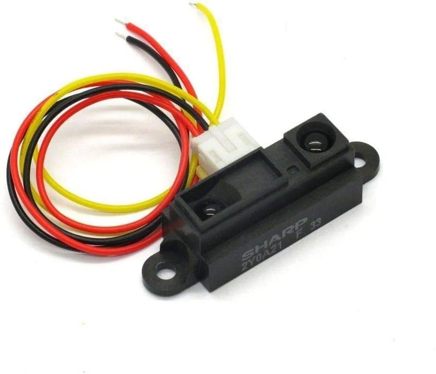
Sharp GP2Y0A21YK0F
Analog infrared distance sensor using triangulation. Industry standard for accurate mid-range measurement.
Range: 10–80 cm · analog output · triangulation.
Sharp GP2Y0A02YK0F
Extended-range variant for applications requiring longer detection distances.
Range: 20–150 cm · analog output · 5 V operation.
How IR triangulation works
Unlike simple IR proximity sensors that just detect presence, triangulation sensors (like the Sharp GP2Y series) project an IR beam and use a position-sensitive detector (PSD) to measure the angle of the reflected light. The closer the object, the larger the angle — allowing precise distance calculation.
Sharp IR sensor code:
const int irPin = A0;

void setup() {
    Serial.begin(115200);
}

void loop() {
    int rawValue = analogRead(irPin);
    float voltage = rawValue * (5.0 / 1023.0);

    // Approximate formula for GP2Y0A21 (10-80 cm)
    // Distance = 27.86 / (Voltage - 0.42)
    float distance = 27.86 / (voltage - 0.42);

    // Constrain to valid range
    distance = constrain(distance, 10, 80);

    Serial.print("Distance: ");
    Serial.print(distance);
    Serial.println(" cm");

    delay(100);
}
3. Laser distance sensors (time-of-flight)
Time-of-Flight (ToF) sensors use laser or LED light and measure the time it takes for photons to travel to an object and back. This provides extremely accurate distance measurements in a compact form factor.
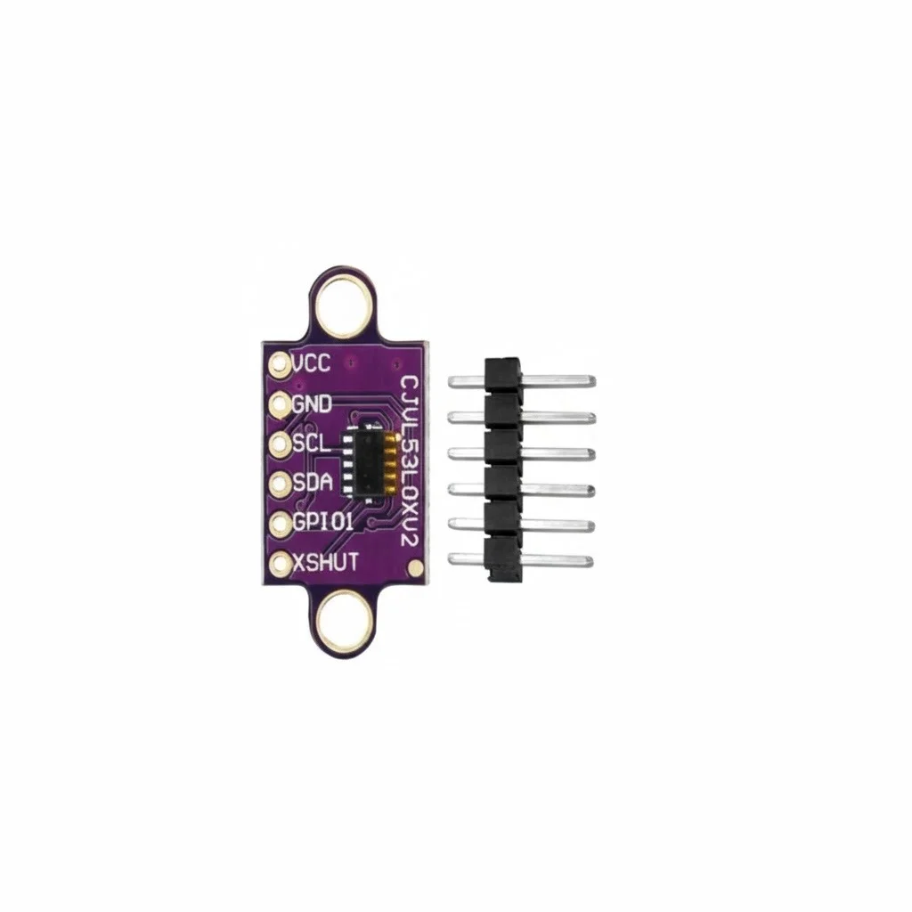
VL53L0X
World’s smallest ToF sensor. I²C interface, perfect for drones, robots, and gesture detection.
Range: 50–1,200 mm · I²C · ±3% accuracy.
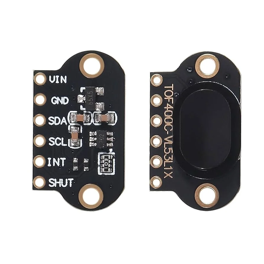
VL53L1X
Extended-range version with programmable FOV (field of view). Excellent for lidar applications.
Range: 40–4,000 mm · programmable FOV · 940 nm laser.
ToF vs triangulation
| Feature | Time-of-Flight (ToF) | Triangulation |
|---|---|---|
| Measurement method | Measures light travel time | Measures reflection angle |
| Range | 30 mm – 4 m+ (VL53L1X) | 10 cm – 1.5 m typical |
| Accuracy | ±1–3% typically | ±5–10% typical |
| Size | Very compact (few mm) | Larger (requires baseline) |
| Cost | $5–$15 for modules | $8–$20 for Sharp sensors |
| Sunlight immunity | Good (with filtering) | Poor (affected by ambient IR) |
VL53L0X code example:
#include "Adafruit_VL53L0X.h"

Adafruit_VL53L0X lox = Adafruit_VL53L0X();

void setup() {
    Serial.begin(115200);

    if (!lox.begin()) {
        Serial.println("Failed to find VL53L0X sensor!");
        while(1);
    }
    Serial.println("VL53L0X Ready!");
}

void loop() {
    VL53L0X_RangingMeasurementData_t measure;

    lox.rangingTest(&measure, false);

    if (measure.RangeStatus != 4) {  // Valid reading
        Serial.print("Distance: ");
        Serial.print(measure.RangeMilliMeter);
        Serial.println(" mm");
    } else {
        Serial.println("Out of range");
    }

    delay(100);
}
4. ToF cameras (depth imaging)
ToF cameras take the single-point ToF concept and extend it to capture entire depth images. Each pixel measures distance independently, creating a 3D depth map of the scene.
How ToF cameras work
There are two main approaches:
- Direct ToF (dToF): measures actual pulse travel time. Used in LiDAR and high-precision systems.
- Indirect ToF (iToF): measures phase shift of modulated light. More common in consumer devices due to lower cost.
iToF cameras emit modulated light (typically sinusoidal) and measure the phase difference between transmitted and received signals. The phase shift directly correlates to distance:
Distance = (c × φ) / (4π × f_mod)

Where:
c = Speed of light (3×10⁸ m/s)
φ = Phase shift (radians)
f_mod = Modulation frequency
Applications of ToF cameras
- Gesture recognition (Microsoft Kinect, Leap Motion).
- Autonomous vehicles and drones.
- 3D scanning and room mapping.
- Augmented reality (AR) devices.
- Industrial automation and bin-picking.
5. PMD (photonic mixer device) technology
PMD sensors are a specialised form of ToF imaging that uses photonic mixing at the pixel level. Each pixel contains a demodulator that directly correlates the incoming light with the reference modulation signal.
PMD technology powers many commercial ToF cameras including the pmd[vision] series and is used in smartphone face recognition systems (like iPhone’s TrueDepth).
PMD vs structured light vs stereo
| Technology | Method | Best for |
|---|---|---|
| PMD / ToF | Phase measurement of modulated light | Real-time depth, mobile devices |
| Structured light | Projects patterns, analyses distortion | 3D scanning, static scenes |
| Stereo vision | Two cameras, triangulation | Outdoor/bright light, texture-rich scenes |
6. Industrial & precision sensors
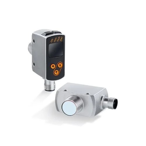
For industrial applications requiring micrometre-level precision, specialised sensors are used:
Laser displacement sensors (triangulation)
These high-precision sensors project a laser spot and use a CMOS/CCD array to detect the reflection position. Unlike ToF, they measure the angle of reflection for sub-micron accuracy.
- Keyence LK-G series: 0.01 µm resolution, 1,000 mm range.
- Micro-Epsilon optoNCDT: nanometre resolution for precision measurement.
Confocal chromatic sensors
Use chromatic aberration of lenses to measure distance. Different wavelengths focus at different distances — the reflected wavelength indicates the exact distance.
Capacitive / eddy-current sensors
Non-optical solutions for extreme precision (nanometres) at very short ranges. Used in semiconductor manufacturing and precision positioning.
7. Choosing the right sensor
Key factors to consider
- Range: what minimum and maximum distances do you need?
- Accuracy: is ±1 cm acceptable or do you need sub-mm precision?
- Speed: how fast do you need readings? (Hz)
- Environment: indoor/outdoor? Temperature extremes? Dust/moisture?
- Power: battery-powered devices need low-power options.
- Interface: I²C, SPI, UART, or analog?
- Cost: budget for your project scale.
8. Summary
| Sensor type | Range | Accuracy | Cost | Best use |
|---|---|---|---|---|
| Ultrasonic (HC-SR04) | 2–400 cm | ±3 mm | $1–$5 | Robotics, parking sensors |
| IR triangulation (Sharp) | 10–150 cm | ±5% | $8–$15 | Mid-range detection |
| Laser ToF (VL53L0X) | 5–120 cm | ±3% | $5–$10 | Precision, gesture, drones |
| Long-range ToF (VL53L1X) | 4–400 cm | ±3% | $10–$15 | LiDAR, robotics |
| ToF camera | 10 cm – 10 m | ±1–2% | $100–$500 | 3D imaging, AR/VR |
| Industrial laser | 0.1–1,000 mm | ±0.01 µm | $500+ | Precision manufacturing |
- Ultrasonic sensors are affordable and work in any lighting, but have wide beam angles.
- IR triangulation offers good accuracy but is affected by ambient light.
- ToF sensors (VL53L0X/L1X) provide the best balance of accuracy, size, and cost.
- ToF cameras capture full depth images for 3D applications.
- PMD technology enables high-speed, accurate depth sensing in compact form factors.
- Choose your sensor based on range, accuracy, environment, and budget requirements.