🔌 Calculate Wire Size
📏 AWG Wire Size Comparison
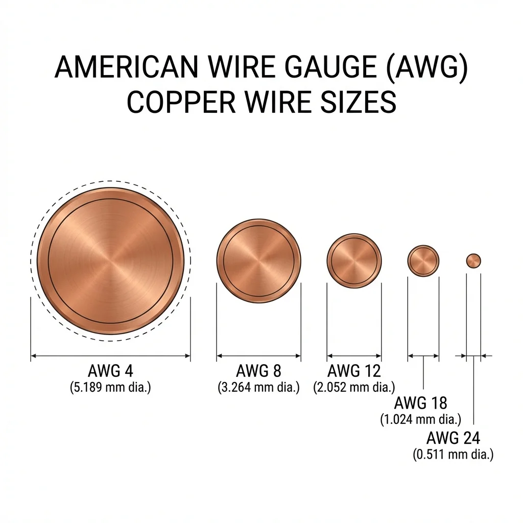
Figure 1: Cross-section comparison of common AWG wire sizes showing relative diameter differences
📐 Understanding AWG (American Wire Gauge)
The American Wire Gauge (AWG) is the standardized wire gauge system used predominantly in North America for measuring the diameter of electrically conducting wire. The AWG system uses an inverse relationship: lower gauge numbers indicate thicker wires.
Key AWG Principles
- Every 3 gauge decrease doubles the wire cross-sectional area
- Every 6 gauge decrease doubles the wire diameter
- AWG 0000 (4/0) is the thickest standard size at 11.68mm diameter
- AWG 40 is among the thinnest at 0.08mm diameter
| AWG | Diameter (mm) | Area (mm²) | Resistance (Ω/km) | Max Amps (Chassis) |
|---|---|---|---|---|
| 4 | 5.19 | 21.2 | 0.815 | 60A |
| 6 | 4.11 | 13.3 | 1.30 | 40A |
| 8 | 3.26 | 8.37 | 2.06 | 30A |
| 10 | 2.59 | 5.26 | 3.28 | 25A |
| 12 | 2.05 | 3.31 | 5.21 | 20A |
| 14 | 1.63 | 2.08 | 8.28 | 15A |
| 16 | 1.29 | 1.31 | 13.2 | 10A |
| 18 | 1.02 | 0.82 | 21.0 | 5A |
| 20 | 0.81 | 0.52 | 33.3 | 3A |
| 22 | 0.64 | 0.33 | 53.0 | 2A |
✈️ Wire Gauge in Critical Industries
Selecting the correct wire gauge is not just about efficiency—in many industries, it's a matter of life and death. Undersized wires can cause overheating, fires, equipment failure, or even catastrophic accidents.
⚠️ Critical Safety Notice
In aerospace, automotive, and marine applications, wire gauge selection must account for altitude, temperature extremes, vibration, and redundancy requirements. Always consult industry-specific standards (MIL-SPEC, SAE, etc.) for critical applications.
✈️ Aerospace Industry
Aircraft wiring must withstand extreme temperatures (-65°F to +260°F), altitude pressure changes, vibration, and electromagnetic interference. Weight is critical—every gram matters. Standards like MIL-DTL-22759 specify wire requirements for aviation.
🚗 Automotive Industry
Vehicle wiring faces engine heat, road vibration, moisture, and salt exposure. Modern vehicles contain over 1,500 wires spanning 1+ mile of total length. SAE J1128 defines automotive wire standards.
🚢 Marine Applications
Marine wiring must resist saltwater corrosion, humidity, and comply with ABYC standards. Tinned copper is often required. Larger gauges compensate for voltage drop over long runs on boats.
🏭 Industrial & Manufacturing
Factory environments require wires rated for oil resistance, flexibility (robotic arms), and high-temperature operations. NEC codes govern commercial/industrial installations.
Why Aircraft Wiring is Especially Critical
Aircraft electrical systems operate under unique constraints that make proper wire selection essential:
- Altitude Effects: Lower air pressure reduces cooling efficiency and changes current-carrying capacity
- Weight Penalties: Oversized wiring adds weight, increasing fuel consumption—but undersized wiring risks fire
- Redundancy: Critical systems require duplicate wiring routed through different paths
- Fire Prevention: Wire insulation must be flame-retardant and self-extinguishing
- EMI Shielding: Avionics wiring requires protection from electromagnetic interference
- Bundle Considerations: Wire bundles derate ampacity due to reduced heat dissipation
📉 Understanding Voltage Drop
Voltage drop is the reduction in voltage as electrical current flows through a wire. It's caused by the wire's inherent resistance and increases with:
- Higher current: More current = more voltage drop
- Longer distance: Longer wires have more resistance
- Smaller wire gauge: Thinner wires have higher resistance per foot
- Higher temperature: Resistance increases with heat
Recommended Maximum Voltage Drop
| Application | Max Voltage Drop | Rationale |
|---|---|---|
| Sensitive Electronics | 2% | Prevents undervoltage issues |
| General Circuits | 3% | NEC recommendation |
| Motor Circuits | 3% | Ensures proper motor operation |
| Feeder Circuits | 2% | Combined with branch = 5% max |
| Non-Critical Loads | 5-10% | Lighting, heating elements |