If you’ve ever tried to use GPIO pins 34, 35, 36, 37, 38, or 39 as outputs on your ESP32 and found that digitalWrite() simply doesn’t work, you’re not alone. This is one of the most common frustrations for ESP32 beginners. The answer lies in the hardware architecture of the ESP32 chip itself.
1. The hardware reason
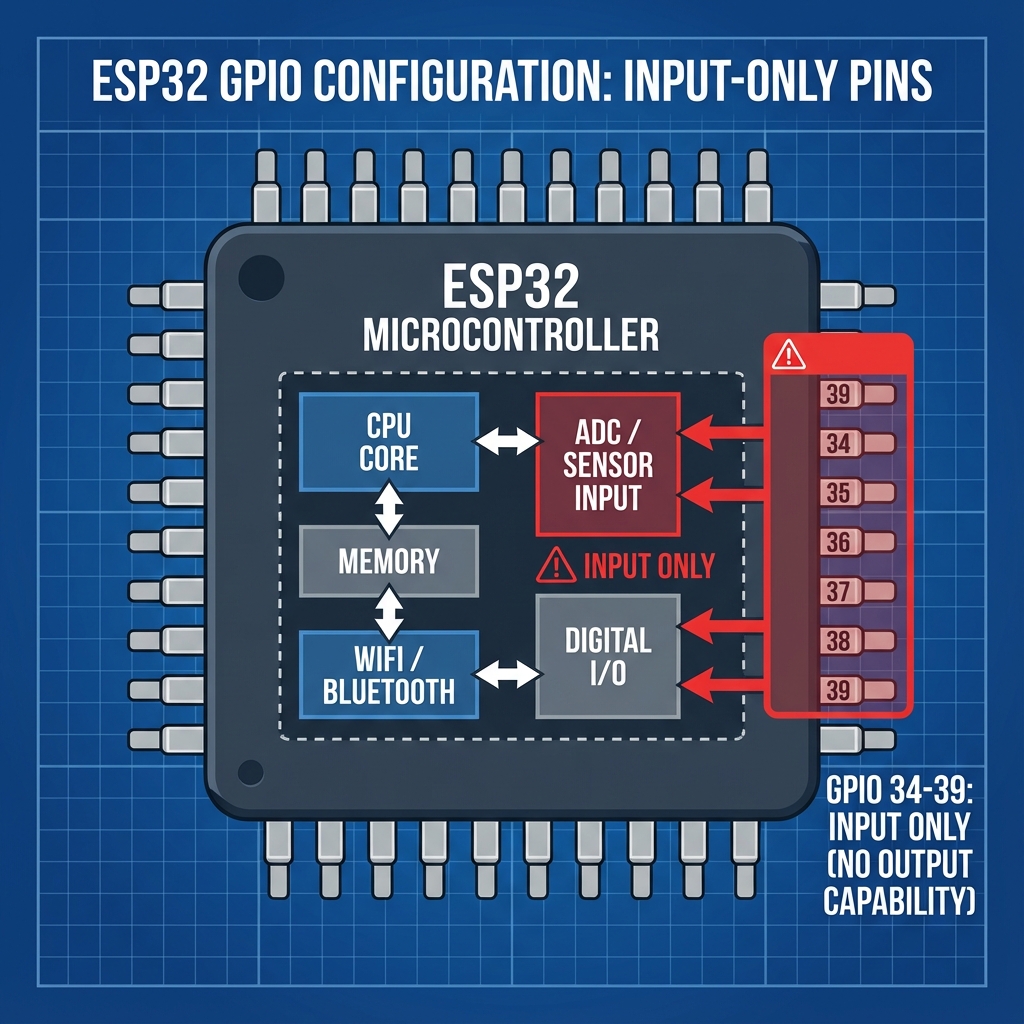
The ESP32 chip is designed with different types of GPIO pins. While most GPIO pins (0–33) have both input and output capabilities, pins 34–39 are specifically designed as input-only pins.
Looking at the ESP32’s internal architecture:
- GPIO 0–33: full bidirectional I/O with push-pull and open-drain output drivers
- GPIO 34–39: input-only pins with no output driver transistors
These pins are connected directly to the internal ADC (Analog-to-Digital Converter) and are optimized for high-impedance analog sensing. The silicon simply doesn’t include the output stage transistors for these pins.
2. Which pins exactly?
Here’s a complete list of the input-only pins on ESP32:
| GPIO pin | ADC channel | Common use |
|---|---|---|
| GPIO 34 | ADC1_CH6 | Analog input, sensor reading |
| GPIO 35 | ADC1_CH7 | Analog input, potentiometer |
| GPIO 36 (VP) | ADC1_CH0 | Sensor VP, high-precision ADC |
| GPIO 37 | ADC1_CH1 | Analog input (not exposed on all boards) |
| GPIO 38 | ADC1_CH2 | Analog input (not exposed on all boards) |
| GPIO 39 (VN) | ADC1_CH3 | Sensor VN, high-precision ADC |
Note: on many ESP32 dev boards (like the ESP32-DevKitC), GPIO 37 and 38 are not broken out to pins and are used internally.
3. Why did Espressif design it this way?
There are several engineering reasons for this design decision:
A. Silicon area optimization
Output drivers require additional transistors (typically a push-pull pair). By omitting these on six pins, Espressif saved valuable silicon real estate, reducing chip cost and power consumption.
B. Dedicated analog inputs
These pins are connected to ADC1 (Analog-to-Digital Converter 1). ADC1 is special because it works even when WiFi is active (unlike ADC2). Having dedicated input-only pins ensures:
- Lower noise for analog measurements
- No accidental output driver interference
- Higher input impedance for sensitive sensors
C. Pin count constraints
The ESP32 has limited package pins. Espressif needed to balance between GPIO count and other dedicated functions (power, crystal, flash, etc.). Making some pins input-only was a practical trade-off.
4. Common symptoms when you try to use them as outputs
Here’s what happens when you mistakenly try to use these pins as outputs:
// This code will NOT work!
void setup() {
    pinMode(34, OUTPUT);  // Silently ignored
    pinMode(35, OUTPUT);  // Silently ignored
}

void loop() {
    digitalWrite(34, HIGH);  // Pin stays LOW
    delay(500);
    digitalWrite(34, LOW);   // No change
    delay(500);
}
Symptoms you’ll observe:
- No compiler or upload errors
- The pin stays at whatever voltage level the external circuit pulls it to
- LEDs connected to these pins won’t light up
- Relays or transistors won’t trigger
5. How to check if a pin is input-only
You can write a quick test function to verify pin capabilities:
void testPinOutput(int pin) {
    Serial.print("Testing GPIO ");
    Serial.print(pin);
    Serial.print(": ");

    pinMode(pin, OUTPUT);

    // Try to set HIGH
    digitalWrite(pin, HIGH);
    delayMicroseconds(100);
    int highRead = digitalRead(pin);

    // Try to set LOW
    digitalWrite(pin, LOW);
    delayMicroseconds(100);
    int lowRead = digitalRead(pin);

    if (highRead == HIGH && lowRead == LOW) {
        Serial.println("OUTPUT capable");
    } else {
        Serial.println("INPUT-ONLY (or externally pulled)");
    }
}

void setup() {
    Serial.begin(115200);
    delay(1000);

    // Test specific pins
    testPinOutput(33);  // Should work
    testPinOutput(34);  // Will report input-only
    testPinOutput(35);  // Will report input-only
}
6. Which pins should you use for outputs?
7. Alternative solutions
If you’ve run out of output pins, consider these alternatives:
A. Use a GPIO expander
I²C GPIO expanders like MCP23017 or PCF8574 add 8–16 additional I/O pins using just 2 ESP32 pins (SDA/SCL).
// Using MCP23017 with Adafruit library
#include <Adafruit_MCP23X17.h>

Adafruit_MCP23X17 mcp;

void setup() {
    mcp.begin_I2C();
    mcp.pinMode(0, OUTPUT);  // Expander pin 0 as output
}

void loop() {
    mcp.digitalWrite(0, HIGH);
    delay(500);
    mcp.digitalWrite(0, LOW);
    delay(500);
}
B. Use shift registers
A 74HC595 shift register can provide 8 outputs using only 3 ESP32 pins. Chain multiple for even more outputs.
C. Multiplex with transistors
Use matrix techniques with transistors to control many outputs with fewer GPIO pins (common in LED matrices).
8. ESP32-S2, S3, and C3 differences
Different ESP32 variants have different input-only pin configurations:
| ESP32 variant | Input-only pins |
|---|---|
| ESP32 (original) | GPIO 34, 35, 36, 37, 38, 39 |
| ESP32-S2 | GPIO 46 |
| ESP32-S3 | None (all GPIO are bidirectional) |
| ESP32-C3 | None (but fewer total GPIO) |
If you need maximum flexibility, the ESP32-S3 is an excellent choice as all its GPIO pins support both input and output.