
Have you ever encountered a ghost in your circuit? A button that seems to trigger itself, or a sensor reading that jumps randomly even when nothing is happening? In the world of digital electronics, these “ghosts” are almost always caused by floating pins.
To fix this, we use two simple yet vital components: pull-up and pull-down resistors. In this guide, we’ll dive deep into why they are essential for your microcontrollers like the ESP32 and Arduino.
1. The problem: the dreaded floating state
Digital inputs are designed to detect two states: HIGH (voltage) and LOW (ground). However, when a pin is not connected to anything (e.g. a button is open), it isn’t “zero” — it’s floating.
Floating pins act like miniature antennas, picking up electromagnetic interference (EMI) from the air, nearby power lines, or even your hand. The result is a pin that rapidly oscillates between HIGH and LOW, causing unpredictable behaviour in your code.
2. The pull-up resistor
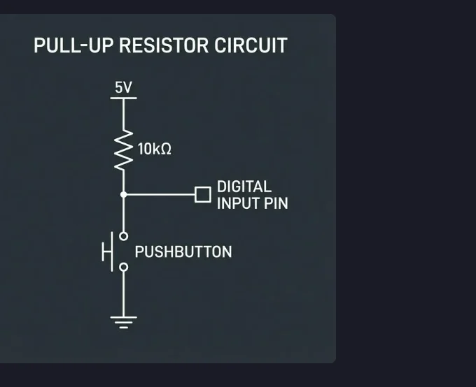
A pull-up resistor connects the input pin to the supply voltage (VCC). This ensures that when the switch is open, the pin is “pulled up” to a stable HIGH state.
When you press the button, the pin is connected directly to ground, overpowering the resistor and pulling the signal LOW. This is why many buttons in electronics are active-low.
// Pull-up example: turning on an LED (active-low)
const int buttonPin = 2; // Button connected to Pin 2 and GND
const int ledPin = 13;   // Built-in LED

void setup() {
  // Use INPUT_PULLUP to enable the internal resistor (no external resistor needed!)
  pinMode(buttonPin, INPUT_PULLUP);
  pinMode(ledPin, OUTPUT);
}

void loop() {
  int state = digitalRead(buttonPin);
  // In a pull-up circuit, the pin is LOW when pressed
  if (state == LOW) {
    digitalWrite(ledPin, HIGH);
  } else {
    digitalWrite(ledPin, LOW);
  }
}3. The pull-down resistor
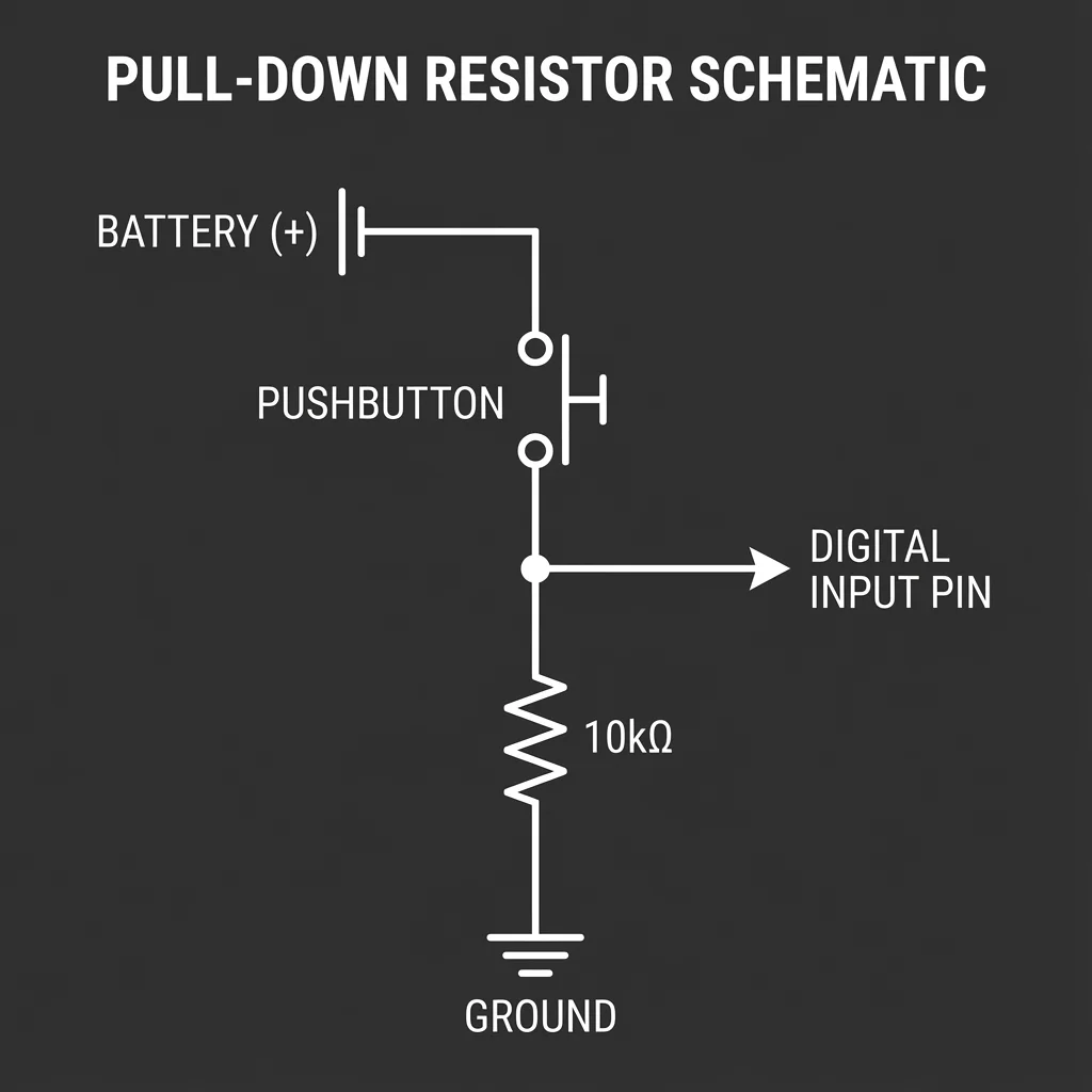
A pull-down resistor does the opposite: it connects the input pin to ground (GND). This keeps the pin in a stable LOW state whenever the switch is open. When the switch is closed, it connects the pin to VCC, pulling it HIGH.
// Pull-down example: turning on an LED (active-high)
const int buttonPin = 2; // Button connected to 5V and Pin 2
const int ledPin = 13;   // Built-in LED

void setup() {
  pinMode(buttonPin, INPUT); // Requires external pull-down resistor
  pinMode(ledPin, OUTPUT);
}

void loop() {
  int state = digitalRead(buttonPin);
  // In a pull-down circuit, the pin is HIGH when pressed
  if (state == HIGH) {
    digitalWrite(ledPin, HIGH);
  } else {
    digitalWrite(ledPin, LOW);
  }
}
4. Choosing a suitable value
Choosing the right resistor value is a balance between power consumption and noise immunity. If the value is too low, you waste power. If it’s too high, the pin can still pick up noise.
| Value | Common use case | Pros / cons |
|---|---|---|
| 1 kΩ – 4.7 kΩ | High-speed communication (I²C) | Strong pull, fast signal transitions, but higher current draw. |
| 10 kΩ | Standard buttons & switches | The “sweet spot” — reliable state with very low power waste. |
| 47 kΩ – 100 kΩ | Battery-powered sensors | Ultra-low power, but susceptible to noise in “dirty” environments. |
5. Why it’s critical for digital GPIOs
Microcontrollers like the ESP32 and Arduino have high-input-impedance pins. They require very little current to detect a state change, which makes them incredibly sensitive to noise.
Without pull-up or pull-down resistors, the high-speed GPIO clocks can interpret noise as valid data pulses, leading to:
- Intermittent system crashes.
- False interrupts triggering.
- Incorrect sensor data interpretation.
- Significant power consumption due to constant switching.
6. ESP32 specifics: which pins to use?
On the ESP32, most GPIOs (0–33) have software-configurable internal pull-up and pull-down resistors. There are important exceptions though:
For all other pins, you can enable the internal resistors in code:
pinMode(pin, INPUT_PULLUP);   // Enable internal pull-up
pinMode(pin, INPUT_PULLDOWN); // Enable internal pull-down (ESP32 only)