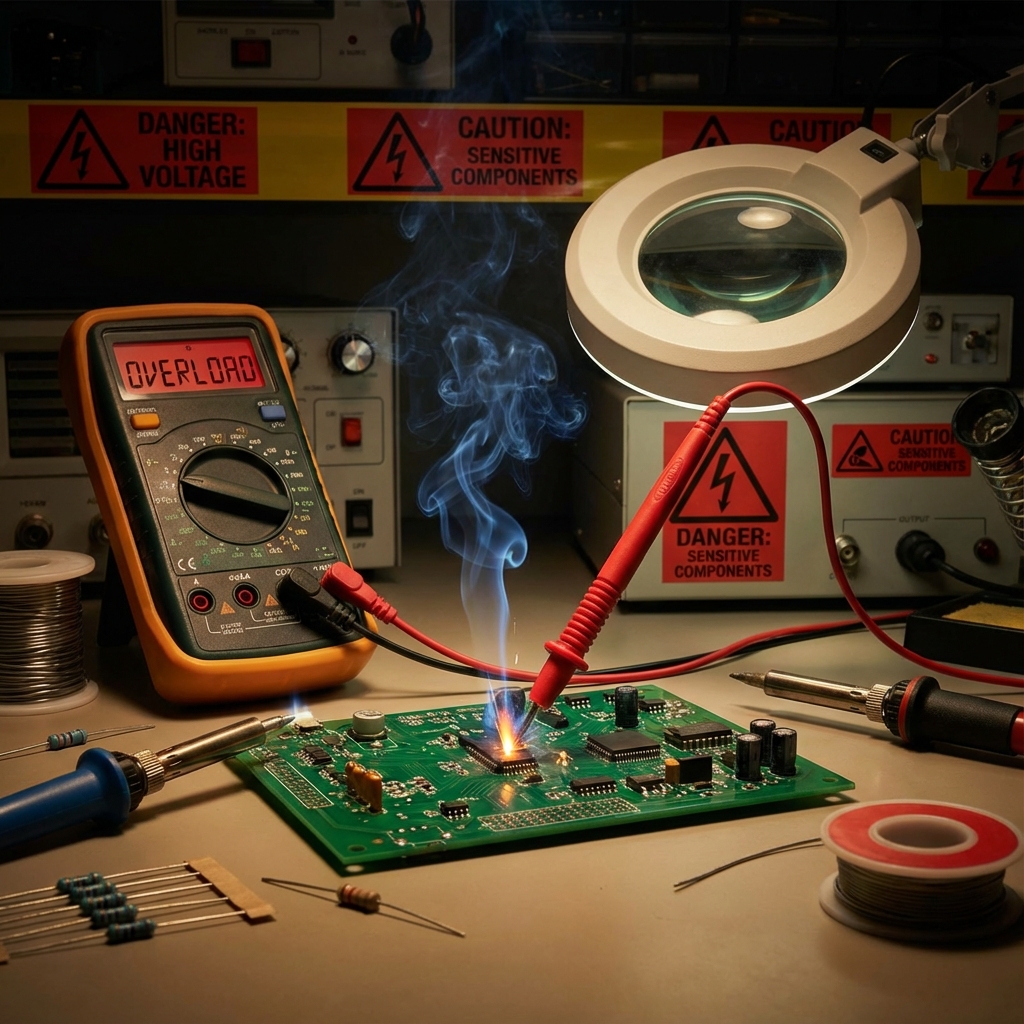
A multimeter is one of the most essential tools in any maker’s arsenal. But in the hands of someone who doesn’t fully understand its operation, it can quickly transform from a diagnostic tool into a circuit-destroying weapon. This guide covers the most common mistakes that damage circuits, blow fuses, and destroy components.
Mistake #1: measuring current in parallel (voltage-mode confusion)
This is the most common and most destructive multimeter mistake. It happens when you try to measure current but place the probes in parallel across a component, or when you forget to move the dial from amperage to voltage mode.
What goes wrong
When set to measure current (amps), a multimeter has near-zero internal resistance. This is by design — current measurement requires the meter to be placed in series with the circuit.
If you accidentally place the probes across a voltage source (in parallel) while in current mode:
// What you're essentially doing:
Power Supply (+) ----[MULTIMETER ~0Ω]---- Power Supply (-)

// This is a SHORT CIRCUIT!
// Current = Voltage / Resistance = 5V / 0.01Ω = 500A!
This is basic Ohm’s law in action — the relationship between voltage, current, and resistance is unforgiving.
How to avoid it
- Always check your dial setting before connecting probes
- Double-check which jacks your leads are plugged into
- Remember: current = series, voltage = parallel
- When measuring current, break the circuit and insert the meter in-line
Mistake #2: leaving probes in the amperage jack
Many multimeters have separate jacks for current measurement (usually marked “10A” or “mA/A”). A deadly habit is to leave the red probe in the amperage jack after finishing a current measurement.
The trap
Later, you go to measure voltage. You turn the dial to “V,” but your probe is still in the current jack. You touch the probes to a power rail… BANG! Short circuit.
| Probe position | Dial setting | Result |
|---|---|---|
| V/Ω jack | Voltage | Correct measurement |
| V/Ω jack | Amperage | No reading (wrong mode) |
| A/mA jack | Voltage | SHORT CIRCUIT! |
| A/mA jack | Amperage | Correct (if in series) |
Best practice
Make it a habit to always return the red probe to the V/Ω jack after any current measurement. Some high-end multimeters beep if you try to measure voltage with the probe in the wrong jack.
Mistake #3: measuring resistance on powered circuits
Resistance measurement sends a small current through the component under test to calculate its resistance (using Ohm’s law). If the circuit is powered, you’re now mixing the meter’s test current with the circuit’s current.
What happens
- Incorrect readings: you’ll get garbage values because external voltages interfere
- Meter damage: the external voltage can damage the meter’s ohmmeter circuit
- Component damage: sensitive components may be affected by the unexpected conditions
Mistake #4: exceeding voltage / current ratings
Every multimeter has maximum ratings for voltage and current. Exceeding these can destroy the meter or cause a dangerous failure.
CAT ratings explained
Multimeters are rated by CAT (category) levels for different environments:
| Rating | Environment | Examples |
|---|---|---|
| CAT I | Low-energy electronics | Battery circuits, signal-level work |
| CAT II | Household outlets | Plugged-in appliances, outlets |
| CAT III | Distribution wiring | Breaker panels, fixed installations |
| CAT IV | Utility connections | Service entrance, meter base |
A cheap CAT I-rated multimeter used on a CAT III circuit can explode during a transient spike.
Mistake #5: not checking / replacing fuses
Most multimeters have internal fuses to protect against over-current. After a short circuit or overload, these fuses may blow, but the meter might still work for voltage measurements.
The sneaky problem
You try to measure current, but the reading is always zero. You assume the circuit is broken, spend hours debugging, only to realize the multimeter’s current fuse is blown.
How to check
- Set your meter to resistance (Ω) mode
- Insert probes into the current measurement jacks
- Touch the probe tips together
- A good fuse shows near-zero resistance
- A blown fuse shows OL / infinite resistance
// Self-test for multimeter current fuse:
Dial: Ω (Resistance)
Red Probe: mA or 10A jack (the one you want to test)
Black Probe: COM

Touch probes together:
Reading ~0.1-1Ω = Fuse OK
Reading OL/∞    = Fuse BLOWN
Mistake #6: using the wrong range
While most modern multimeters are auto-ranging, many budget meters require manual range selection. Setting the wrong range leads to problems:
Range too low
- Display shows “OL” or “1” (overload)
- On old meters, this can damage the meter movement
- For current, this can blow the internal fuse
Range too high
- Very low precision (e.g. measuring 5 V on a 1000 V range shows “5” with no decimal places)
- Might miss important details like ripple voltage
Best practice
Start with the highest range and work your way down for the best resolution while avoiding overload.
Mistake #7: ignoring AC vs DC settings
Measuring AC voltage while set to DC (or vice versa) gives incorrect readings and can lead to dangerous assumptions.
| Signal type | DC setting | AC setting |
|---|---|---|
| Pure DC (battery) | Correct reading | ~0 V (no AC component) |
| Pure AC (mains) | ~0 V or erratic | Correct RMS reading |
| DC + ripple | Shows average DC | Shows only ripple component |
When debugging power supplies, you may need to check both AC and DC to understand the full picture (DC level + ripple).
Mistake #8: probing without looking
“Tenting” or blindly stabbing probes around a circuit without looking is dangerous:
- Slipping probes can bridge adjacent pins or traces
- You might touch high-voltage sections you weren’t aware of
- Sharp probe tips can scratch through solder mask creating shorts
Mistake #9: continuity testing on sensitive components
Continuity mode sends a small current (typically 0.5–1 mA at 2–3 V) through the circuit. While safe for most components, it can cause issues with:
- LEDs: may briefly flash (usually harmless)
- Logic gates: the test voltage can trigger inputs
- Charged capacitors: can give false readings or unexpected behaviour
- ESD-sensitive components: always handle with care
Mistake #10: not understanding true RMS
Budget multimeters use “averaging” to measure AC, which only works correctly for pure sine waves. Non-sinusoidal signals (PWM, square waves, distorted AC) give incorrect readings.
True RMS vs average-reading
| Signal type | Average-reading meter | True-RMS meter |
|---|---|---|
| Pure sine wave | Accurate | Accurate |
| Square wave | ~11% error | Accurate |
| PWM / pulse | Wildly incorrect | Accurate |
| Distorted mains | May be 20%+ off | Accurate |
If you work with switching power supplies, motor drives, or any non-sinusoidal AC, invest in a true-RMS multimeter.
Quick reference: safe multimeter practices
- Never measure voltage with probes in the amp jack — this causes short circuits
- Always disconnect power before measuring resistance
- Check dial and probe positions before every measurement
- Start with the highest range and work down
- Replace blown fuses with the correct rating
- Use a true-RMS meter for non-sinusoidal signals
- Respect mains voltage — it can kill
A multimeter is an incredibly powerful diagnostic tool when used correctly. By understanding these common mistakes and developing safe habits, you’ll protect both your circuits and yourself.