If you’ve ever wanted to dim an LED or control the speed of a DC motor, you’ve likely used Pulse Width Modulation (PWM). While simple in concept, PWM is the backbone of efficient power delivery in modern electronics.
In this guide, we’ll explore how PWM works and why it is the preferred method for controlling high-power loads using MOSFETs.
1. What is PWM?
PWM is a technique for getting analog results with digital means. Microcontroller pins can only be ON (5 V/3.3 V) or OFF (GND). By switching a pin on and off extremely fast, we can simulate an intermediate voltage.
The key metric is the duty cycle: the percentage of time the signal is HIGH versus the total time of one pulse period.
- 25% duty cycle: signal is ON for 1/4 of the time. Equivalent to ~1.25 V on a 5 V system.
- 50% duty cycle: signal is ON for 1/2 of the time. Equivalent to 2.5 V.
- 100% duty cycle: signal is always ON. Full 5 V.
2. Handling high power: the MOSFET
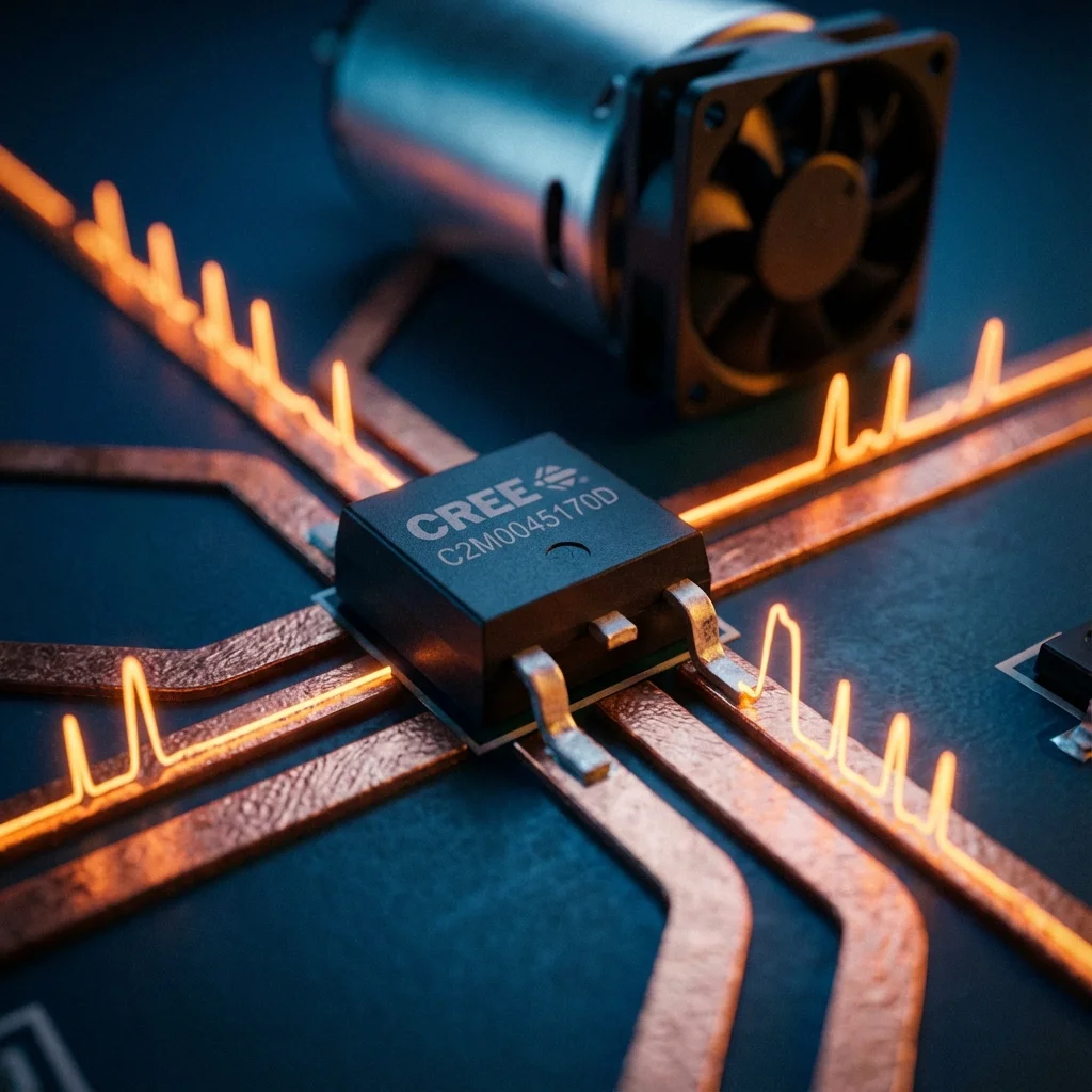
Microcontroller pins can only provide a few milliamps (typically 20–40 mA). To control a 10 A motor or a high-power LED strip, we need a “muscle” component: the MOSFET (Metal-Oxide-Semiconductor Field-Effect Transistor).
A MOSFET acts like a high-speed electronic switch. We apply the PWM signal to the Gate, which controls the flow of current between the Drain and the Source.
3. The importance of the flyback diode
When controlling inductive loads like motors or solenoids, you must include a flyback diode (also known as a snubber diode) in parallel with the load.
When the PWM signal turns the MOSFET OFF, the magnetic field in the motor collapses, creating a massive voltage spike (Back EMF). Without a diode to safely recirculate this current, these spikes can instantly destroy your MOSFET or even your microcontroller.
4. Code example: Arduino motor control
Controlling PWM on an Arduino is as simple as using the analogWrite() function, which outputs a PWM signal on specific pins.
// Simple PWM Motor Speed Control
const int motorPin = 9; // PWM capable pin
int speed = 0;
void setup() {
pinMode(motorPin, OUTPUT);
}
void loop() {
// Fade motor speed up
for (speed = 0; speed <= 255; speed++) {
analogWrite(motorPin, speed);
delay(10);
}
// Fade motor speed down
for (speed = 255; speed >= 0; speed--) {
analogWrite(motorPin, speed);
delay(10);
}
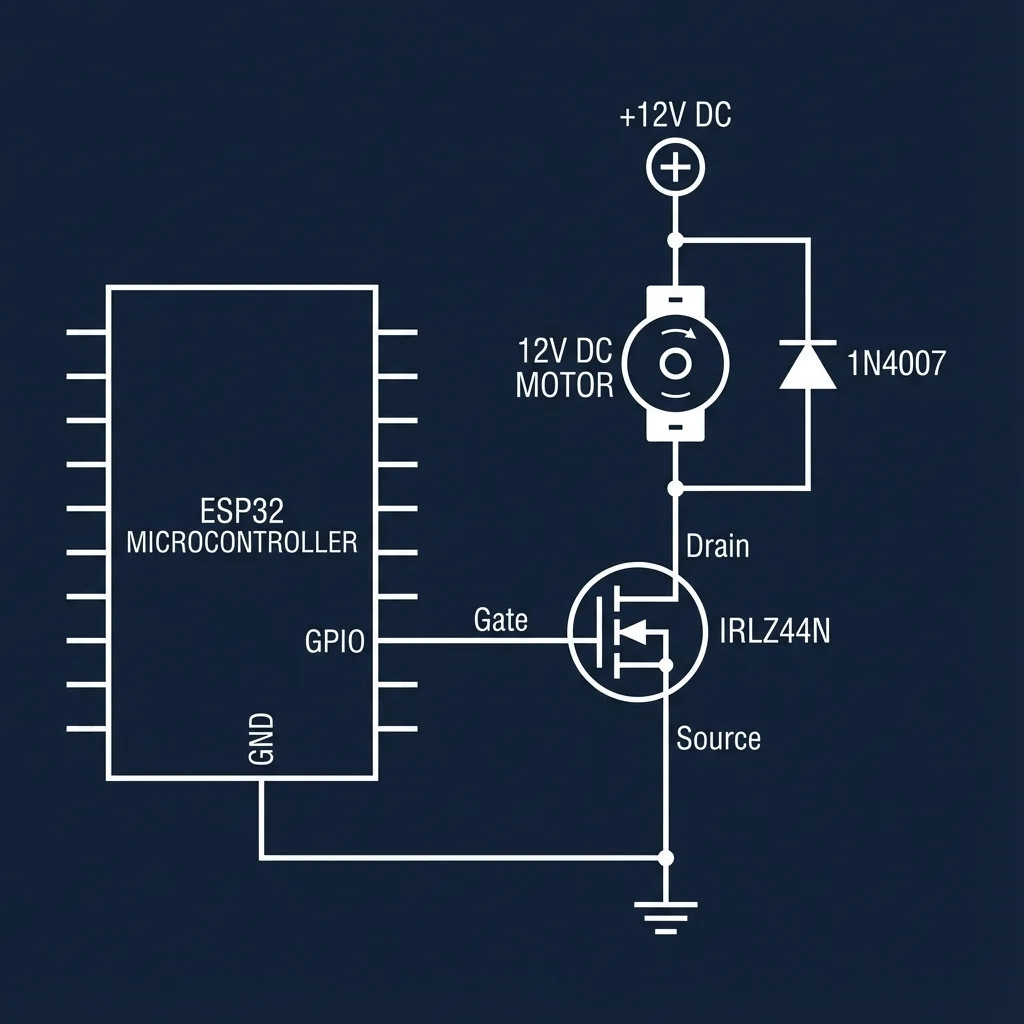
}5. Real-world application: ESP32 + MOSFET + 12 V motor
For more advanced projects, the ESP32 offers powerful PWM capabilities. In this setup, we use an N-channel MOSFET to switch a high-current 12 V motor. The ESP32 provides the low-power control signal to the MOSFET’s Gate.
On the ESP32, while analogWrite() is available in newer Arduino cores, the standard approach uses the LEDC hardware peripheral, which provides 16 channels, custom frequencies, and 1–15 bit resolution.
// ESP32 PWM Control (LEDC)
const int motorPin = 18; // GPIO 18
const int freq = 5000;
const int ledChannel = 0;
const int resolution = 8;

void setup() {
  // Configure LEDC PWM
  ledcSetup(ledChannel, freq, resolution);

  // Attach the channel to the GPIO
  ledcAttachPin(motorPin, ledChannel);
}

void loop() {
  // Gradually increase motor speed
  for(int dutyCycle = 0; dutyCycle <= 255; dutyCycle++){
    ledcWrite(ledChannel, dutyCycle);
    delay(15);
  }
}