Structural Beam Bending
When a beam is loaded, it deforms. The amount of vertical displacement is called **Deflection**. Controlling deflection is critical for safety and user comfort—you don't want a floor that feels bouncy!
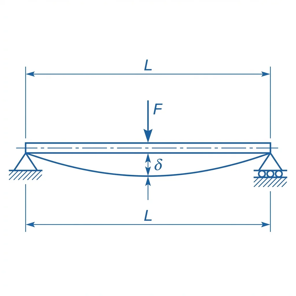
Figure 1: Simply supported beam with a central load F and deflection delta.
The Deflection Formula
For a **simply supported beam** with a point load at the center, the maximum deflection (δ) occurs directly under the load:
δ = (P×L³)/(48×E×I)
Where:
- P: Applied load or force (N)
- L: Span length of the beam (mm)
- E: Modulus of elasticity (MPa, though we input GPa in the tool)
- I: Area moment of inertia (mm⁴)
How to Reduce Deflection
If your beam bends too much, you have four options based on the physics:
- Increase I (Shape): Use a taller beam. Since I depends on height cubed (h³), small increases in height make the beam much stiffer.
- Decrease L (Span): Shorten the distance between supports. Deflection grows with the cube of length (L³).
- Change E (Material): Switch to a stiffer material (e.g., from aluminum to steel).
- Decrease P (Load): Reduce the weight on the beam.