🔗 Mechanical Suite
⚙️ Gear Ratio Calculator
Calculate speed, torque, and mechanical advantage for gear-driven systems. Perfect for robotics, automotive design, and industrial machinery projects.
🔧 Ratio & Torque Solver
📖 Understanding Gear Ratios
A gear ratio is the relationship between the number of teeth on two gears that are meshed or two pulleys connected with a common belt. It defines how much the speed or torque of the input shaft is transformed at the output shaft.
Torque vs. Speed Trade-off
In any gear system, there is a fundamental trade-off governed by the law of conservation of energy (excluding losses to friction):
- To Increase Torque: Use a smaller driver gear to turn a larger follower gear (Reduction). This slows down the output but multiplies strength.
- To Increase Speed: Use a larger driver gear to turn a smaller follower gear (Overdrive). This increases speed but reduces the available torque.
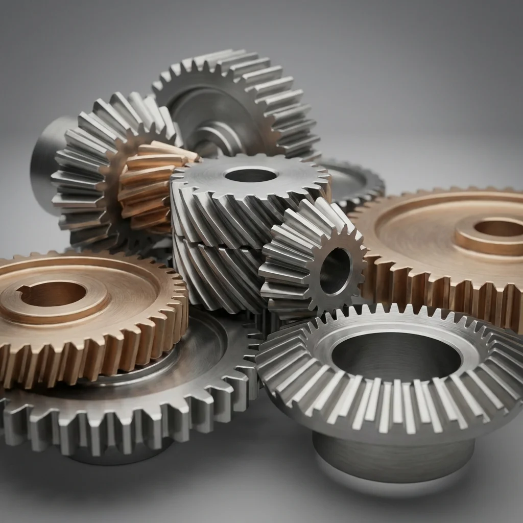
📐 Types of Gear Engagement
Different gear types are designed for specific orientations and load requirements.
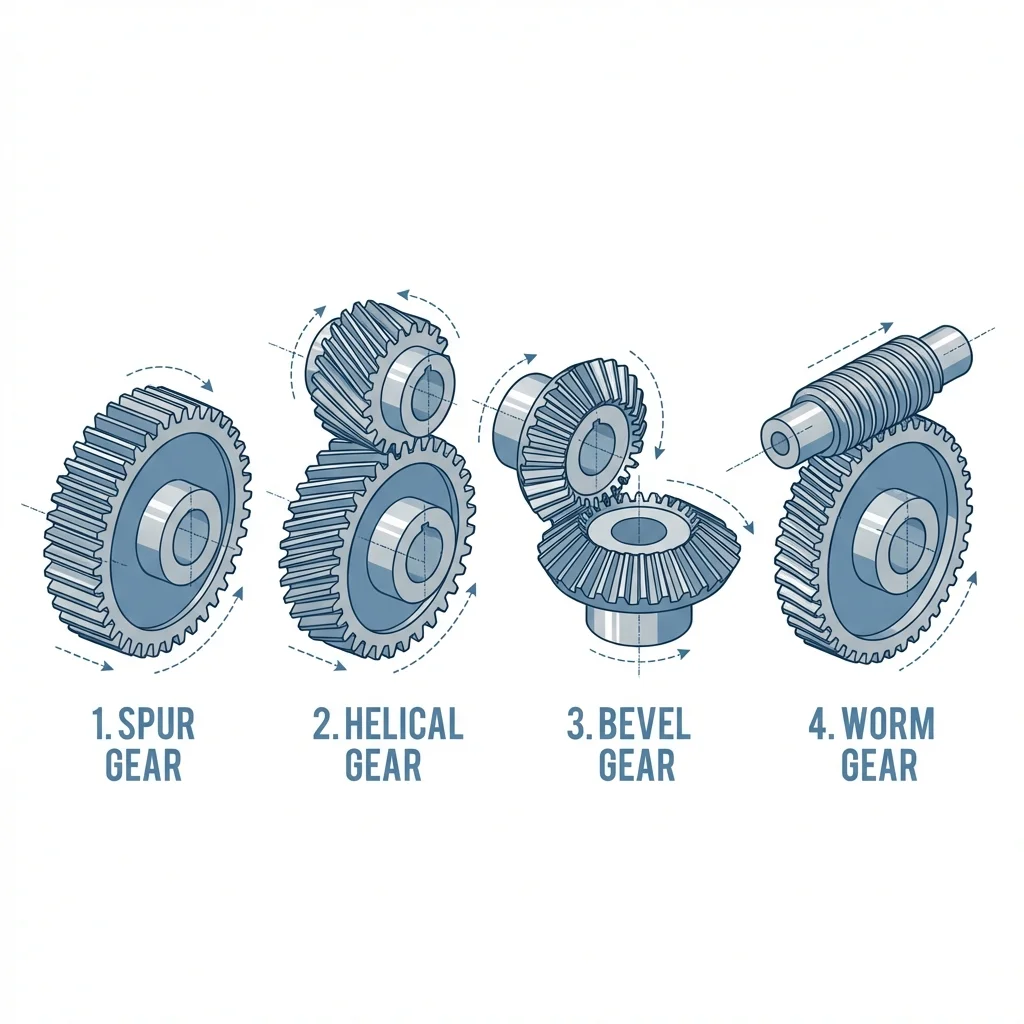
⚙️ Spur Gears
Used for parallel shafts. The simplest and most common type, though they can be noisy at high speeds.
🌀 Helical Gears
Similar to spur gears but teeth are cut at an angle. This allows for smoother and quieter operation under high loads.
⛰️ Bevel Gears
Designed to transfer motion between intersecting shafts, typically at a 90-degree angle (like a car differential).
🐛 Worm Gears
A spiral screw (worm) meshes with a gear. Provides very high reduction ratios in a compact space and prevents back-driving.