Connect an oscilloscope probe to a node and the signal changes. Swap a speaker cable for a thin wire and the bass disappears. Measure voltage at the far end of a long cable and read something different than at the source. All three share the same root cause: impedance mismatch. Understanding impedance — what it is, how input and output impedance affect your circuit, and when matching matters — is one of the most practical skills in electronics.
1. Resistance, Reactance, and Impedance
In a DC circuit the only opposition to current is resistance R — a real number, frequency-independent. AC circuits add two more players:
- Inductive reactance XL = 2πfL — rises with frequency. An inductor is nearly a short circuit at DC and an open circuit at very high frequency.
- Capacitive reactance XC = 1 / (2πfC) — falls with frequency. A capacitor blocks DC (XC → ∞) and passes high frequencies freely (XC → 0).
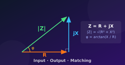
- Impedance Z = R + jX — the complex sum where X = XL − XC. The magnitude |Z| = √(R² + X²) gives the total opposition to current. The phase angle φ = arctan(X / R) tells you whether current leads or lags voltage.
2. The Impedance Triangle
Plot R on the real axis and X on the imaginary axis. The impedance vector Z is the hypotenuse — its length is |Z| and its angle from the real axis is φ.
3. Reactance at Common Frequencies
The table below shows how XC and XL vary across the audio and RF range for two common values: 100 nF cap and 1 mH inductor.
| Frequency | XC — 100 nF | XL — 1 mH |
|---|---|---|
| 100 Hz | 15 900 Ω | 0.63 Ω |
| 1 kHz | 1 590 Ω | 6.3 Ω |
| 10 kHz | 159 Ω | 63 Ω |
| 100 kHz | 15.9 Ω | 628 Ω |
| 1 MHz | 1.6 Ω | 6 280 Ω |
The crossover point — where XC = XL — is the resonant frequency f₀ = 1 / (2π√LC) ≈ 503 kHz for these values. At resonance the reactances cancel, leaving only R.
4. Input Impedance — Why Higher Is Better
Every circuit input has an input impedance Zin. It behaves exactly like an impedance connected from the input pin to ground — which forms a voltage divider with the source’s own output impedance ZS.
5. Output Impedance — Why Lower Is Better
Every real source — a battery, a function generator, an amplifier output — has an output impedance Zout. It acts like a series impedance in the Thévenin equivalent: it drops voltage whenever current flows into the load.
6. Impedance Matching — Maximum Power Transfer
When you care not about voltage but about power delivered to a load — antennas, RF amplifiers, audio output stages — a different rule applies.
7. Why Impedance Matters in Practice
- Signal integrity: a high-impedance sensor driving a low-impedance input loses most of its signal to the voltage divider. Add a unity-gain buffer (voltage follower) to decouple them. Read the voltage follower guide →
- Cable length: a long cable adds capacitance (≈ 100 pF/m). Combined with a 10 kΩ source impedance it forms a low-pass RC filter. At 10 kHz a 1 m cable can already roll off the signal.
- RF and antenna work: a 50 Ω coax driven by a mismatched source creates reflections. SWR (standing wave ratio) measures the mismatch; 1:1 is perfect, anything above 2:1 wastes significant power.
- Audio: headphone amplifiers specify output impedance < 1/8 of the headphone impedance (Damping Factor rule) to avoid frequency response changes driven by the headphone’s voice-coil inductance.
Try It in the Calculator
The Impedance Builder lets you compose series/parallel R, L, and C networks and see the impedance magnitude and phase across a swept frequency range — instantly.
For the theory behind how capacitive reactance and inductive reactance interact in series RLC circuits, see the Capacitive Reactance topic and the Phasors Introduction.