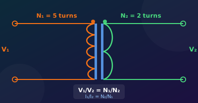
The transformer is one of the most elegant inventions in electrical engineering. No moving parts, no active components, no power supply — just two coils of wire and a magnetic core that can step voltage up or down, isolate circuits from the mains, or couple an RF signal across a frequency band. This guide covers how transformers work, the most common types, how to read the spec sheet, and what engineers need to know before specifying one.
1. How a Transformer Works
Faraday’s law is the engine: a changing magnetic flux through a coil induces a voltage. In a transformer, alternating current in the primary winding creates a changing magnetic flux in the shared core. That flux threads through the secondary winding and induces a secondary voltage whose magnitude depends entirely on the turns ratio.
- Energy transfer is via the magnetic field, not via electrical conduction — the two windings are galvanically isolated (no direct wire connection between them).
- Transformers only work with AC (or pulsed DC). They cannot transform steady DC because a static field induces no voltage.
- In an ideal transformer (lossless, infinite permeability core) power in equals power out: V1 × I1 = V2 × I2.
2. The Turns Ratio
The turns ratio n = N1 / N2 governs everything:
- Voltage scales with turns: V2 / V1 = N2 / N1
- Current scales inversely: I2 / I1 = N1 / N2
- Impedance scales as the square: Zreflected = ZL × (N1 / N2)²
3. Types of Transformers
Step-Down Transformer
N1 > N2. Reduces voltage, increases current. The mains transformer in most power supplies (e.g., 230 V → 12 V) is a step-down type.
Step-Up Transformer
N2 > N1. Increases voltage, reduces current. Grid substations use step-up transformers to raise generator output to hundreds of kV for efficient long-distance transmission (lower I → lower I²R loss).
Isolation Transformer
N1 = N2 (1:1 ratio). No voltage change — the purpose is galvanic isolation. Breaks the ground reference connection between primary and secondary. Used in medical equipment, oscilloscope probes, and anywhere a floating supply is required for safety.
Autotransformer
A single tapped winding shared between primary and secondary. Smaller and cheaper than a two-winding design for the same VA rating, but provides no galvanic isolation. Common in motor starters, Variacs (continuously variable), and power conditioning.
Toroidal Transformer
Wound on a doughnut-shaped core. The closed magnetic path gives very low leakage flux and low EMI radiation — preferred in high-fidelity audio amplifiers and medical instruments. Heavier to mount but significantly quieter magnetically than EI-core designs.
Current Transformer (CT)
The load (measured conductor) forms a single-turn primary. The secondary (many turns) produces a small proportional current for measurement. CTs power smart-meter clamps and current-sensing protection relays. Never open-circuit the secondary of a CT under load — the full primary MMF drives the core into saturation and produces a dangerously high secondary voltage.
RF and IF Transformers
Air-core or ferrite-core, wound for use at kHz to GHz. Primary roles: impedance matching between amplifier stages, balun conversion (balanced ↔ unbalanced), and bandpass filtering when combined with tuning capacitors. Ferrite material is chosen to minimise core loss at the operating frequency.
4. Key Specifications
Before specifying or buying a transformer, understand these parameters:
- VA rating — apparent power capacity. A 50 VA transformer can continuously deliver 50 V at 1 A or 25 V at 2 A. Exceeding the VA rating causes excessive core heating.
- Turns ratio — sets the voltage conversion. Always verify under load because winding resistance causes regulation droop.
- Efficiency (η) — typically 95–99% for power transformers, lower for small signal types. Lost power goes into core losses and copper losses.
- Regulation (%) — the percentage voltage drop from no-load to full-load. A 10% regulation transformer rated 12 V may put out 13.2 V unloaded.
- Core losses — present even with no load. Eddy-current losses and hysteresis losses both heat the core continuously.
- Copper losses (I²R) — the resistive loss in the winding wire. Rise quadratically with current; dominant at high load.
- Insulation class — the temperature rating (Class A = 105°C, Class B = 130°C, Class F = 155°C, Class H = 180°C). Dictates operating environment and overload capacity.
- Frequency range — mains transformers are designed for 50 Hz or 60 Hz. Ferrite-core switching transformers operate from kHz to MHz. Using a 50 Hz transformer at 400 Hz reduces core losses; using it at lower frequency risks core saturation.
5. Core Materials
- Silicon steel (laminated): used in 50/60 Hz power transformers. Laminations break up eddy-current paths. Saturates around 1.5–2 T.
- Ferrite: ceramic magnetic material. High resistivity (low eddy currents), used from 10 kHz to > 1 MHz in SMPS and RF transformers. Lower saturation flux than steel (≈ 0.3–0.5 T).
- Amorphous / nanocrystalline: very low core loss at 50/60 Hz. Used in premium distribution transformers and current transformers where efficiency matters.
- Air core: no saturation, no hysteresis loss, but very weak coupling. Used at RF and microwave where even ferrite losses are too high.
- Powered iron: iron particles in a resin binder. Lower permeability than ferrite but good at high-frequency, high-current applications (RF chokes, SMPS inductors).
6. Common Applications by Type
| Type | Typical Application |
|---|---|
| Step-down (EI core) | Linear bench PSU, door-bell transformer, low-voltage lighting |
| Step-up | HV lab supply, inverter output stage, CRT display flyback |
| Isolation 1:1 | Medical equipment, oscilloscope probes, floating supplies |
| Autotransformer | Motor soft-starters, Variac, 120 V ↔ 220 V travel adaptors |
| Toroidal | Hi-fi amplifiers, low-noise instruments, medical devices |
| Current transformer | Energy meters, protective relays, clamp-on ammeters |
| Ferrite (SMPS) | Flyback, forward, push-pull converter isolation stages |
| RF / IF balun | Antenna matching, receiver front-end, mixer port coupling |
Try the Calculator
Use the Transformer Calculator to compute turns ratios, reflected impedance, and voltage regulation under different load conditions.
For AC fundamentals behind transformer operation, see the AC Fundamentals topic and the Controlled Rectifiers topic.